This is part one of a series. In this post we talk about what we’ve done and why, and in the next post we talk about how in detail.
In this time of Covid-19 I was looking for a way to help. Because of our g2core project I have an unusual amount of manufacturing capability in my household, but I was conserving my resources for the right project. My friends together have dozens of 3D printers, all working around the clock to print face shields, masks, and other PPE-adjacent items, so I didn’t feel I could add much there.
Then I saw a tweet by YouTuber Destin of Smarter Every Day where there is a BVM (Bag-Valve-Mask, a.k.a. AmbuBag) being mechanically squeezed to make a bush-fix ventilator. A BVM is a device you’ve likely seen if you’ve watched any movie involving someone in an ambulance. This device is not intended to replace the expensive and rare respirators, but instead help those that don’t need them yet. I thought: “Now that I can do!”
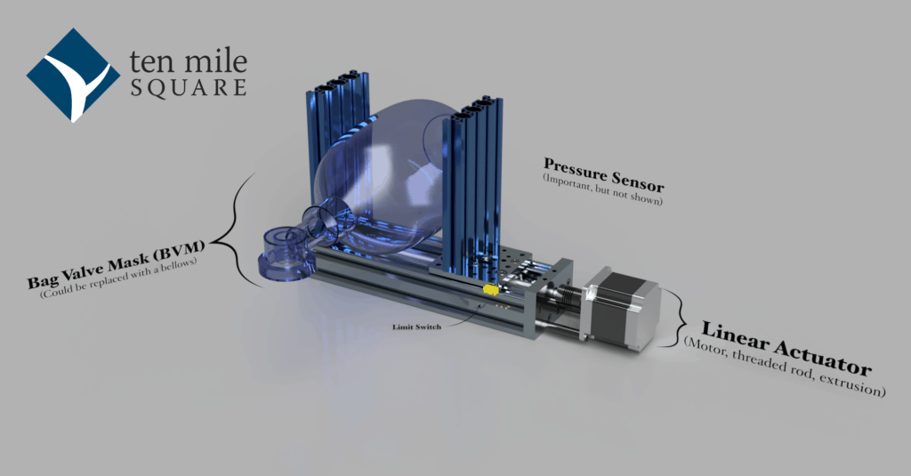
Jumping ahead a little bit, here’s a diagram of the current state of the resulting project, and there is a video later in the post:

After consulting with the internet (for example, this project from MIT is often cited) and some Respiratory Therapists who use ventilators in their day-to-day work, my colleague Riley Porter and I gathered a short list of major requirements, keeping in mind that the details and minor requirements are constantly shifting as more is learned about COVID-19 and how to treat it. This is not an exhaustive list:
- Pressure is key – it must be measured accurately and managed carefully
- Volume is important as well, but there are a few means of control where volume is not directly managed
- Controls must include:
- Peak pressure target
- Breaths-per-minute
- Inhale, exhale (I/E) ratio
- Ideally be remotely controllable
- Alerting, alarms, and error reporting is critical
- The condition of the patient may effect the timing of the pressure curve and acceptance of volume, so it must be made flexible and reactive
I feel it’s important that this be fully open-source. It needs to be freely copyable, easily peer reviewed, and easily adjusted for regionally available parts. It’s also important that components of this project be used independently in other projects. These are all important to enable rapid development and collaborative design.
I looked around and there are quite a few other projects with similar goals. None of the open-source projects that I found were managing pressure in a truly configurable and reactive way. (I have since found this list, which refers to several exhaustive lists of requirements, but also shows that few if any other open projects manage pressure quite the same way.)
I mentioned the g2core project before. It’s our motion-control system (hardware+firmware with some host-side software) for CNC machines like mills such as this one from Bantam Tools, laser cutters, and 3D printers. It’s also used for some CNC-adjacent stuff like the wire benders from Pensa Labs.
Normally g2core executes motion following pre-determined programs (written in gcode) that come out of CAM programs. A host computer like a Raspberry Pi sends short JSON commands and Gcode to configure the machine and make it move, and g2core sends back a stream of JSON for telemetry. g2core executes these to control stepper motors with an advanced “jerk-limited” planning profile (more info here) that, in brief, is designed to get the most power and reliability out of inexpensive and commonly available open-loop motors.
All of that we can do, for us that’s easy stuff since we’ve already written it over the last ten years and it’s reliable and tested. We recently did a project building a cable-driven robot that can do highly accurate drawings over a large floor area. Cables (or in this case something that typically would be called “ropes”) are very flexible, can only be pulled on (not pushed), and stretch over time and under stress. Because of this we needed to add encoders and load-cells to measure exact movement and cable stress levels.
The work done on that project directly relates to this one. Lungs, all of the tubing (called “circuit”), valves, and other equipment make for a wildly non-linear problem space, much like cables. Also like cables, we can only control the output directly in one direction – we can add pressure but cannot reduce it directly. For example, with the BVM, when the pressure is released even slightly, the valve releases all of the pressure quickly. Even when holding pressure evenly, the valve leaks slightly.
In the next blog post, I’ll cover more detail of our current state, with such details as jerk-controlled PID output and using a state machine for error detection. For now, here’s a video demonstrating the current state of the project:
Continue reading part two of the series, where we go into more detail.
